Blog
In a field that evolves daily, staying ahead means staying informed.
Explore in-depth articles designed to help you solve complex challenges,
maximize your machine’s ROI.
Stay ahead in a competitive market.


In a field that evolves daily, staying ahead means staying informed.
Explore in-depth articles designed to help you solve complex challenges,
maximize your machine’s ROI.
Stay ahead in a competitive market.
News | Oct-18-2026 | Mimowork
Quick Answer
To achieve deep black laser marking on anodized aluminum, a MOPA fiber laser is often a strong choice because its adjustable pulse duration and frequency allow more precise control over the surface-marking process. The key is to create a dark, uniform mark without unnecessarily removing or damaging the anodized layer. The final result depends on the coating, laser parameters, focusing conditions, and hatch spacing, so testing on the actual workpiece is essential.
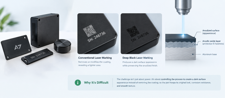
Anodized aluminum is widely used for product housings, control panels, nameplates, electronic enclosures, and industrial identification labels. Its anodic oxide layer provides corrosion resistance, surface hardness, and a suitable base for decorative finishes. However, achieving a rich black mark is not simply a matter of increasing laser power.
Conventional laser marking often removes or modifies the anodized coating, exposing a lighter area underneath. This can produce a sharp, high-contrast white or silver mark, particularly on black anodized aluminum. Although this effect is useful for serial numbers and logos, it does not meet every design requirement.
When the objective is a deep black mark, the process must be controlled differently. Instead of treating the coating as material that needs to be removed, the operator needs to establish conditions that produce a dark surface appearance while preserving the integrity of the anodized finish.
This distinction matters in applications where the part must retain its original appearance, protective properties, and smooth surface texture. It also explains why two aluminum components that look identical may respond differently to the same laser settings.
A successful process starts with understanding the surface rather than immediately changing machine parameters.
Anodizing creates a controlled aluminum oxide layer on the metal surface. Depending on the production process, this layer may be naturally clear, dyed black, or finished in another color. Its thickness, porosity, dye composition, and sealing conditions can all influence the laser response.
For certain anodized surfaces, a MOPA fiber laser can produce dark gray to deep black marks through controlled surface modification while minimizing coating removal. This is different from conventional engraving, where the objective is to remove material and create a lighter exposed area.
The important limitation is that not every anodized coating will produce the same black-marking effect. A setting that works on one supplier’s aluminum plate may create a gray mark, uneven coloration, or coating damage on another.
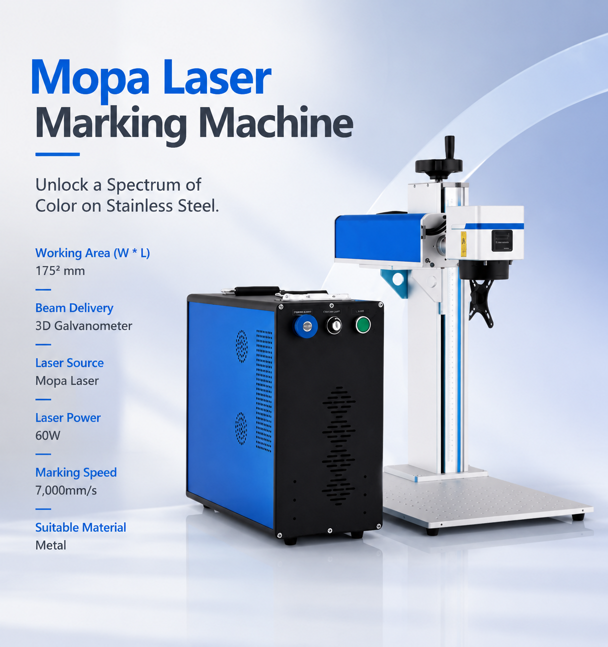
MOPA fiber lasers offer adjustable pulse duration alongside other controllable parameters. This gives the operator greater flexibility when balancing marking contrast, surface appearance, and thermal input.
A conventional fiber laser may still be appropriate for many anodized-aluminum applications, particularly when white marking or coating removal is desired. However, when the specification calls for a uniform black appearance with limited surface damage, MOPA technology is often worth evaluating first.
Choosing a suitable laser marking machine is only part of the solution. The laser source, optical configuration, material finish, and marking strategy must work together to achieve the required result.
Before running a test, confirm whether the workpiece has clear anodizing, black anodizing, another dyed finish, or a different surface treatment. Do not assume that all aluminum described as anodized will respond in the same way.
If possible, obtain a sample from the actual production batch. Different coating suppliers and finishing processes can produce noticeable differences in marking behavior.
Record the coating type, color, surface texture, and any known sealing treatment. These details help explain why a marking result changes between batches.
Remove fingerprints, dust, oil, and other surface contamination using a cleaning method compatible with the coating. Allow the surface to dry completely before marking.
Position the workpiece securely and ensure that its marking area is flat relative to the focal plane. Even a small change in focus can affect spot size, energy distribution, and visual uniformity.
For nameplates, logos, and small identification codes, consistent positioning is particularly important because slight differences can become obvious when parts are inspected side by side.
Begin with a parameter set recommended for the specific laser source and optical configuration. Avoid copying settings from another machine without confirming that its power, pulse-duration range, lens, and control software are comparable.
The main variables are power, marking speed, pulse frequency, pulse duration, hatch spacing, and the number of passes. These settings interact rather than working independently.
| Parameter | What it influences | Practical adjustment approach |
| Laser power | Overall energy delivered to the surface | Increase cautiously while checking for coating damage |
| Marking speed | Energy exposure along each scan path | Test several speeds to balance darkness and uniformity |
| Pulse frequency | Pulse repetition rate and energy distribution | Evaluate alongside pulse duration and power |
| Pulse duration | Energy delivery within each pulse | Use the available range to find a suitable surface response |
| Hatch spacing | Overlap between adjacent scan lines | Test closer spacing for more uniform coverage |
| Number of passes | Total exposure during processing | Compare a single pass with additional passes only when needed |
| Focus position | Spot size and energy concentration | Maintain consistent focus across the workpiece |
There is no universally correct combination. Increasing power or reducing speed may darken some marks, but it can also increase heat accumulation, change the surface texture, or damage the coating. The best setting is the one that meets the required appearance and durability criteria, not simply the one that produces the darkest sample.
Rather than adjusting several settings at once, create a small test grid. Keep the design, focus, and workpiece conditions consistent while varying one or two parameters at a time.
For example, compare several combinations of speed and pulse duration, then refine the most promising result using frequency and hatch spacing. Label each sample with its settings so that a successful result can be reproduced.
A useful test should evaluate more than color. Inspect the mark for uniformity, edge definition, visible coating damage, roughness, and consistency across filled areas. If the component will be exposed to abrasion, cleaning agents, or outdoor conditions, include an appropriate durability test.
This systematic method is more reliable than repeatedly changing settings based on visual judgment alone.
Hatch spacing controls the distance between adjacent laser scan lines. If the spacing is too wide, gaps may make the black area appear striped or uneven. Closer spacing can improve coverage, but excessive overlap may increase processing time and heat accumulation.
Bidirectional scanning can be efficient for filled shapes, provided the machine maintains consistent marking quality in both directions. For larger logos or broad solid areas, compare different fill patterns and scan directions using the same test conditions.
Small text and fine symbols may require a different approach from large filled shapes. The optimum strategy should reflect the geometry of the artwork, not just the desired color.
Once a satisfactory sample has been produced, inspect it under consistent lighting. Reflections from the aluminum surface can make a mark appear darker or lighter depending on the viewing angle.
Check whether the coating remains intact, whether edges are clean, and whether the marked area has a consistent appearance. For functional components, verify that the process has not affected critical dimensions or surface requirements.
Finally, test repeatability across several workpieces. A single successful sample does not establish a production-ready process. The settings should remain reliable across the expected material and coating variation.
| Problem | Possible cause | What to investigate |
| The mark appears gray instead of black | Inappropriate pulse settings, insufficient coverage, or coating variation | Run a controlled parameter grid and check the anodized finish |
| The black area looks patchy | Uneven coating, inconsistent focus, or insufficient scan overlap | Verify flatness, focus, and hatch spacing |
| The surface becomes rough or damaged | Excessive thermal input or material removal | Reduce exposure and reassess pulse duration and scan strategy |
| Fine text loses definition | Excessive overlap, unsuitable spot size, or excessive energy | Refine focus and use a smaller test design |
| Results vary between batches | Differences in coating thickness, dye, sealing, or surface finish | Validate each material batch before production |
| Marking takes too long | Overly dense filling or unnecessary passes | Optimize the fill strategy without compromising appearance |
One important point: a darker result is not automatically a better result. If the marking process removes too much of the anodized layer, the part may no longer meet its original cosmetic or protective requirements.
For industrial production, quality should be defined before the settings are finalized. A simple visual comparison is useful during initial testing, but repeatable production requires measurable acceptance criteria.
For example, a manufacturer may specify minimum contrast, maximum visible surface damage, acceptable edge definition, and a consistent appearance across a batch. Where appearance is critical, standardized lighting and color measurement can make inspection more repeatable.
Durability should also be considered in context. A decorative logo on an indoor enclosure may have different requirements from a marking on equipment exposed to abrasion, moisture, or cleaning chemicals. If the protective properties of the anodized finish are critical, confirm that the selected process preserves the required performance rather than assuming it does.
Yes, but the result depends on the laser source and the anodized finish. MOPA fiber lasers are often preferred when adjustable pulse duration is needed to produce darker marks with controlled surface modification.
The laser may be removing the anodized layer and exposing the lighter material underneath. This is a common result of conventional marking on colored anodized aluminum. A different marking strategy and suitable laser parameters may be necessary for a dark mark.
No. Higher power can increase material removal and heat input rather than improve black coloration. Power should be evaluated alongside speed, pulse duration, frequency, and hatch spacing.
Deep black laser marking on anodized aluminum requires control over the interaction between the laser and the anodic surface. MOPA technology provides useful flexibility, but consistent results depend on material selection, focusing, scan strategy, and systematic parameter testing.
For manufacturers, the practical goal is not simply to achieve the darkest possible mark. It is to produce a clean, repeatable result that satisfies appearance, durability, and surface-integrity requirements throughout production.
Related guide: What is a Fiber Laser Marking Machine? The Ultimate Guide to Industrial Precision
1.Datalogic, Laser Marking Processes — Reference Guide (PDF). Reference material on laser marking processes, including black marking on anodized aluminum.

News | Sep-14-2026

News | Sep-11-2026